ISABugger
The ISABugger card provides a debugging interface for software developers, consisting of two 8-bit hexadecimal displays and two banks of 8 LEDs, all controlled by the emulated machine. It can be enabled through the Peripherals settings page.
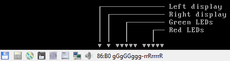
These displays and LEDs are displayed on the status bar as described in the diagram below:
Background
From src/device/bugger.c:
Implementation of the ISA Bus (de)Bugger expansion card
sold as a DIY kit in the late 1980's in The Netherlands.
This card was a assemble-yourself 8bit ISA addon card for
PC and AT systems that had several tools to aid in low-
level debugging (mostly for faulty BIOSes, bootloaders
and system kernels...)

The standard version had a total of 16 LEDs (8 RED, plus
8 GREEN), two 7-segment displays and one 8-position DIP
switch block on board for use as debugging tools.

The "Plus" version, added an extra 2 7-segment displays,
as well as a very simple RS-232 serial interface that
could be used as a mini-console terminal.
Registers
The ISABugger’s control registers can be accessed through the following operations on I/O ports 0x7a and 0x7b:
Writing: write the register’s index to port
0x7a, then write the value to port0x7b.Reading: write the register’s index to port
0x7a, then read the value from port0x7b.Index reading: the last register index written to port
0x7acan be read back from the same port. The most significant bit is always set, as an indicator that the ISABugger is enabled.
Note
The ISABugger I/O ports only support byte (inb/outb) operations. Word (inw/outw) and dword (inl/outl) operations will result in undefined behavior; so will selecting or attempting to read back an unknown register index, or performing an illegal operation such as reading from a write-only register.
Register reference
Index 0x00 - Red LEDs (write-only)
Index 0x01 - Green LEDs (write-only)
Each LED bank shows a binary representation of the 8-bit value written to its register, from the most significant bit on the left to the least significant bit on the right. Setting a bit will light up its corresponding LED (displayed as G or R), and clearing a bit will dim its LED (displayed as g or r).
Index 0x02 - Right display (write-only)
Index 0x04 - Left display (write-only)
Each display shows a hexadecimal representation of the 8-bit value written to its register.
Index 0x20 - Serial port data (not implemented) (read/write)
Index 0x40 - Serial port configuration (not implemented) (read/write)
While the aforementioned real ISABugger card is equipped with an independent RS-232 serial interface, that feature is currently not implemented on 86Box in an user-facing manner.
Index 0x80 - Initialize (not implemented) (write-only)
This register has no effect on 86Box, as the emulated ISABugger is always enabled and ready.
Index 0xff - Reset (special)
Writing register index 0xff to port 0x7a will immediately reset all registers to their startup value, clearing all displays and LED banks.
This is a special register which cannot be read or written; writing to port 0x7b immediately after a reset will result in the value being sent to the default register index of 0x00, which corresponds to the red LEDs.