PCI
PCI devices are more complex than ISA devices; they are individually addressable through a device number, and contain a configuration space for configuring several aspects of the device.
Adding a device
PCI devices can be added with the pci_add_card function in the device’s init callback. A PCI slot is automatically selected for the device according to the add_type; if the emulated machine runs out of slots, a DEC 21150 PCI-PCI bridge is automatically deployed to add 9 more slots, and new devices are placed in the secondary PCI bus under it.
Code example: adding a PCI device
#include <86box/device.h>
#include <86box/pci.h>

#define FOO_ONBOARD 0x80000000  /* most significant bit set = on-board */

typedef struct {
    int     slot;
    uint8_t pci_regs[256]; /* 256*8-bit configuration register array */
} foo_t;

static uint8_t
foo_pci_read(int func, int addr, void *priv)
{
    /* Get the device state structure. */
    foo_t *dev = (foo_t *) priv;

    /* Ignore unknown functions. */
    if (func > 0)
        return 0xff;

    /* Read configuration space register. */
    return dev->pci_regs[addr];
}

static void
foo_pci_write(int func, int addr, uint8_t val, void *priv)
{
    /* Get the device state structure. */
    foo_t *dev = (foo_t *) priv;

    /* Ignore unknown functions. */
    if (func > 0)
        return;

    /* Write configuration space register. */
    dev->pci_regs[addr] = val;
}

static void *
foo_init(const device_t *info)
{
    /* Allocate the device state structure. */
    foo_t *dev = /* ... */

    /* Add PCI device. */
    dev->slot = pci_add_card(PCI_ADD_NORMAL, foo_pci_read, foo_pci_write, dev);

    return dev;
}

const device_t foo4321_device = {
    .name = "Foo-4321",
    .internal_name = "foo4321",
    .flags = DEVICE_PCI,
    .local = 4321,
    .init = foo_init,
    /* ... */
};
Parameter |
Description |
|---|---|
|
PCI slot type to add this card to. |
|
Configuration space register read callback. Takes the form of:
|
|
Configuration space register write callback. Takes the form of:
|
|
Opaque pointer passed to this device’s configuration space register read/write callbacks, usually a pointer to a device’s state structure. |
Return value |
|
Slot types
A machine may declare special PCI slots for specific purposes, such as on-board PCI devices which don’t correspond to a physical slot. The add_type parameter to pci_add_card determines which kind of slot the device should be placed in:
PCI_ADD_NORMAL: normal 32-bit PCI slot;PCI_ADD_AGP: AGP slot (AGP is a superset of PCI);PCI_ADD_VIDEO: on-board video controller;PCI_ADD_SCSI: on-board SCSI controller;PCI_ADD_SOUND: on-board sound controller;PCI_ADD_IDE: on-board IDE controller;PCI_ADD_NETWORK: on-board network controller;PCI_ADD_NORTHBRIDGE,PCI_ADD_AGPBRIDGE,PCI_ADD_SOUTHBRIDGE: reserved for the chipset.
A device available both as a discrete card and as an on-board device should have different device_t objects with unique local values to set both variants apart.
Code example: device available as both discrete and on-board
#include <86box/device.h>
#include <86box/pci.h>

#define FOO_ONBOARD 0x80000000  /* most significant bit set = on-board */

typedef struct {
    int slot;
} foo_t;

static void *
foo_init(const device_t *info)
{
    /* Allocate the device state structure. */
    foo_t *dev = /* ... */

    /* Add PCI device. The normal variant goes in any normal slot,
       and the on-board variant goes in the on-board SCSI "slot". */
    dev->slot = pci_add_card((info->local & FOO_ONBOARD) ? PCI_ADD_SCSI : PCI_ADD_NORMAL,
                             foo_pci_read, foo_pci_write, dev);

    return dev;
}

const device_t foo4321_device = {
    .name = "Foo-4321",
    .internal_name = "foo4321",
    .flags = DEVICE_PCI,
    .local = 4321, /* on-board bit not set */
    .init = foo_init,
    /* ... */
};

const device_t foo4321_onboard_device = {
    .name = "Foo-4321 (On-Board)",
    .internal_name = "foo4321_onboard",
    .flags = DEVICE_PCI,
    .local = 4321 | FOO_ONBOARD, /* on-board bit set */
    .init = foo_init,
    /* ... */
};
Configuration space
The PCI configuration space is split into a standard register set from 0x00 through 0x3f, and device-specific registers from 0x40 through 0xff. Not all standard registers are present or writable (partially or fully) on all devices; consult the documentation for the device you’re trying to implement to determine which registers and bits are present or writable.
Note
The documentation for some devices may treat configuration space registers as 16- or 32-bit-wide. Since 86Box works with 8-bit-wide registers, make sure to translate all wider register offsets and bit numbers into individual bytes (in little endian / least significant byte first).
Important
Aside from the configuration space, devices will very often have a different set of registers in I/O or memory space; from now on, “registers” will refer to configuration space registers.
The most important registers in the standard set are:
Offsets |
Register |
Description |
|---|---|---|
|
Vendor ID |
Unique IDs assigned to the device’s vendor (2 bytes) and the device itself (2 more bytes). The PCI ID Repository is a comprehensive repository of many (but not all) known PCI IDs. |
|
Device ID |
|
|
Command |
Control several core aspects of the PCI device:
|
|
Header type |
Usually |
|
Sets the base address for each memory or I/O range provided by this device. |
|
|
Subvendor ID |
Unique vendor (2 bytes) and device (2 bytes) IDs sometimes assigned to different implementations of the same PCI device without having to change the main Vendor and Device IDs.
Usually all |
|
Subsystem ID |
|
|
Expansion ROM |
Base address and enable bit for the device’s option ROM. Must be read-only if the device does not provide an option ROM. |
|
Interrupt Line |
The PIC IRQ number assigned to this device’s interrupt pin (see |
|
Interrupt Pin |
Read-only value indicating the PCI interrupt pin (
|
Multi-function devices
PCI defines the concept of functions, which allow a physical device to contain up to 8 sub-devices (numbered from 0 to 7), each with their own configuration space, and their own resources controlled by Base Address Registers. Most (but not all) multi-function PCI devices are chipset southbridges, which may implement a function for the PCI-ISA bridge (and general configuration), another one for the IDE controller, one or more for USB and so on.
The func parameter passed to a device’s configuration space read/write callbacks provides the function number for which the configuration space is being accessed. There are two main requirements for implementing multi-function devices:
The first function (function
0) must have bit 7 (0x80) of the Header Type (0x0e) register set;Unused functions must return
0xffon all configuration register reads and should ignore writes.
Code example: device with two functions
typedef struct {
    int     slot;
    uint8_t pci_regs[2][256]; /* two 256*8-bit configuration register arrays,
                                 one for each function */
} foo_t;

static uint8_t
foo_pci_read(int func, int addr, void *priv)
{
    /* Get the device state structure. */
    foo_t *dev = (foo_t *) priv;

    /* Read configuration space register on the given function. */
    switch (func) {
        case 0: /* function 0 */
            return dev->pci_regs[0][addr];

        case 1: /* function 1 */
            return dev->pci_regs[1][addr];

        default: /* out of range */
            return 0xff;
    }
}

static void
foo_pci_write(int func, int addr, uint8_t val, void *priv)
{
    /* Get the device state structure. */
    foo_t *dev = (foo_t *) priv;

    /* Write configuration space register on the given function. */
    switch (func) {
        case 0: /* function 0 */
            dev->pci_regs[0][addr] = val;
            break;

        case 1: /* function 1 */
            dev->pci_regs[1][addr] = val;
            break;

        default: /* out of range */
            break;
    }
}

static void
foo_reset(void *priv)
{
    /* Get the device state structure. */
    foo_t *dev = (foo_t *) priv;

    /* Reset PCI configuration registers. */
    memset(dev->pci_regs[0], 0, sizeof(dev->pci_regs[0]));
    memset(dev->pci_regs[0], 0, sizeof(dev->pci_regs[0]));

    /* Write default vendor IDs, device IDs, etc. */

    /* Flag this device as multi-function. */
    dev->pci_regs[0][0x0e] = 0x80;
}

static void *
foo_init(const device_t *info)
{
    /* Allocate the device state structure. */
    foo_t *dev = /* ... */

    /* Add PCI device. No changes are required here for multi-function devices. */
    dev->slot = pci_add_card(PCI_ADD_NORMAL, foo_pci_read, foo_pci_write, dev);

    /* Initialize PCI configuration registers. */
    foo_reset(dev);

    return dev;
}

const device_t foo4321_device = {
    /* ... */
    .init = foo_init,
    .reset = foo_reset,
    /* ... */
};
Base Address Registers
Each function may contain up to six Base Address Registers (BARs), which determine the base and size of a memory or I/O resource provided by the device. The base address may be set by the BIOS and/or operating system during boot. Each 4-byte BAR has two parts:
The most significant bits store the resource’s base address, aligned to its size;
The least significant bits are read-only flags related to the BAR:
Bit 0 is the resource type:
0for memory or1for I/O;Bits 1-3 on memory BARs are positioning flags not really relevant to the context of 86Box;
Bit 1 on I/O BARs is reserved and must be
0.
The aforementioned base address alignment allows software (BIOSes and operating systems) to tell how big a BAR resource is, by checking how many base address bits are writable. All bits ranging from the end of the flags to the start of the base address must be read-only and always read 0; for example, on a memory BAR that is 4 KB (4096 bytes) large, bits 31-12 must be writable (creating a 4096-byte alignment), bits 11-4 must read 0, and bits 3-0 must read the BAR flags.
Note
The minimum BAR sizes are 4 KB for memory and 4 ports for I/O. While memory BARs can technically be as small as 16 bytes, 86Box can only handle device memory in aligned 4 KB increments.
Byte |
|
|
|
|
||||||||||||||||||||||||||||
|---|---|---|---|---|---|---|---|---|---|---|---|---|---|---|---|---|---|---|---|---|---|---|---|---|---|---|---|---|---|---|---|---|
Bit |
31 |
30 |
29 |
28 |
27 |
26 |
25 |
24 |
23 |
22 |
21 |
20 |
19 |
18 |
17 |
16 |
15 |
14 |
13 |
12 |
11 |
10 |
9 |
8 |
7 |
6 |
5 |
4 |
3 |
2 |
1 |
0 |
Value |
Base memory address (4096-byte aligned) |
Always |
Flags |
|
||||||||||||||||||||||||||||
Byte |
|
|
|
|
||||||||||||||||||||||||||||
|---|---|---|---|---|---|---|---|---|---|---|---|---|---|---|---|---|---|---|---|---|---|---|---|---|---|---|---|---|---|---|---|---|
Bit |
31 |
30 |
29 |
28 |
27 |
26 |
25 |
24 |
23 |
22 |
21 |
20 |
19 |
18 |
17 |
16 |
15 |
14 |
13 |
12 |
11 |
10 |
9 |
8 |
7 |
6 |
5 |
4 |
3 |
2 |
1 |
0 |
Value |
Ignored ( |
Base I/O port (64-byte aligned) |
Always |
R |
|
|||||||||||||||||||||||||||
Code example: memory and I/O BARs described above
#include <86box/io.h>
#include <86box/mem.h>

typedef struct {
    uint8_t       pci_regs[256];
    uint16_t      io_base;
    mem_mapping_t mem_mapping;
} foo_t;

static void
foo_remap_mem(foo_t *dev)
{
    if (dev->pci_regs[0x04] & 0x02) {
        /* Memory Space bit set, apply the base address.
           Least significant bits are masked off to maintain 4096-byte alignment.
           We skip reading dev->pci_regs[0x10] as it contains nothing of interest. */
        mem_mapping_set_addr(&dev->mem_mapping,
                             ((dev->pci_regs[0x11] << 8) | (dev->pci_regs[0x12] << 16) | (dev->pci_regs[0x13] << 24)) & 0xfffff000,
                             4096);
    } else {
        /* Memory Space bit not set, disable the mapping. */
        mem_mapping_set_addr(&dev->mem_mapping, 0, 0);
    }
}

static void
foo_remap_io(foo_t *dev)
{
    /* Remove existing I/O handler if present. */
    if (dev->io_base)
        io_removehandler(dev->io_base, 64,
                         foo_io_inb, foo_io_inw, foo_io_inl,
                         foo_io_outb, foo_io_outw, foo_io_outl, dev);

    if (dev->pci_regs[0x04] & 0x01) {
        /* I/O Space bit set, read the base address.
           Least significant bits are masked off to maintain 64-byte alignment. */
        dev->io_base = (dev->pci_regs[0x14] | (dev->pci_regs[0x15] << 8)) & 0xffc0;
    } else {
        /* I/O Space bit not set, don't do anything. */
        dev->io_base = 0;
    }

    /* Add new I/O handler if required. */
    if (dev->io_base)
        io_sethandler(dev->io_base, 64,
                      foo_io_inb, foo_io_inw, foo_io_inl,
                      foo_io_outb, foo_io_outw, foo_io_outl, dev);
}

static void
foo_pci_write(int func, int addr, uint8_t val, void *priv)
{
    /* Get the device state structure. */
    foo_t *dev = (foo_t *) priv;

    /* Ignore unknown functions. */
    if (func > 0)
        return;

    /* Write configuration space register. */
    switch (addr) {
        case 0x04:
            /* Our device only supports the I/O and Memory Space bits of the Command register. */
            dev->pci_regs[addr] = val & 0x03;

            /* Update memory and I/O spaces. */
            foo_remap_mem(dev);
            foo_remap_io(dev);
            break;

        case 0x10:
            /* Least significant byte of the memory BAR is read-only. */
            break;

        case 0x11:
            /* 2nd byte of the memory BAR is masked to maintain 4096-byte alignment. */
            dev->pci_regs[addr] = val & 0xf0;

            /* Update memory space. */
            foo_remap_mem(dev);
            break;

        case 0x12: case 0x13:
            /* 3rd and most significant bytes of the memory BAR are fully writable. */
            dev->pci_regs[addr] = val;

            /* Update memory space. */
            foo_remap_mem(dev);
            break;

        case 0x14:
            /* Least significant byte of the I/O BAR is masked to maintain 64-byte alignment, and
               ORed with the default value's least significant bits so that the flags stay in place. */
            dev->pci_regs[addr] = (val & 0xc0) | (dev->pci_regs[addr] & 0x03);

            /* Update I/O space. */
            foo_remap_io(dev);
            break;

        case 0x15:
            /* Most significant byte of the I/O BAR is fully writable. */
            dev->pci_regs[addr] = val;

            /* Update I/O space. */
            foo_remap_io(dev);
            break;

        case 0x16: case 0x17:
            /* I/O BARs are only 2 bytes long, ignore the rest. */
            break;
    }
}

static void
foo_reset(void *priv)
{
    /* Get the device state structure. */
    foo_t *dev = (foo_t *) dev;

    /* Reset PCI configuration registers. */
    memset(dev->pci_regs, 0, sizeof(dev->pci_regs));

    /* Write default vendor ID, device ID, etc. */

    /* The BAR at 0x10-0x13 is a memory BAR. */
    //dev->pci_regs[0x10] = 0x00; /* least significant bit already not set = memory */

    /* The BAR at 0x14-0x17 is an I/O BAR. */
    dev->pci_regs[0x14] = 0x01; /* least significant bit set = I/O */

    /* Clear all BAR memory mappings and I/O handlers. */
    //dev->pci_regs[0x04] = 0x00; /* Memory and I/O Space bits already cleared */
    foo_remap_mem(dev);
    foo_remap_io(dev);
}

/* Don't forget to add the PCI device on init first. */

const device_t foo4321_device = {
    /* ... */
    .reset = foo_reset,
    /* ... */
};
Option ROM
A PCI function may have an option ROM, which behaves similarly to a memory BAR in that the ROM can be mapped to any address in 32-bit memory space, aligned to its size. As with BARs, the BIOS and/or operating system takes care of mapping; for example, a BIOS will map the primary PCI video card’s ROM to the legacy 0xc0000 address.
The main difference between this register and BARs is that the ROM can be enabled or disabled through bit 0 (0x01) of this register. Both that bit and the Command (0x04) register’s Memory Space bit (bit 1 or 0x02) must be set for the ROM to be accessible.
Note
The minimum size for an option ROM is 4 KB (see the note about 86Box memory limitations in the BAR section), and the maximum size is 16 MB.
Byte |
|
|
|
|
||||||||||||||||||||||||||||
|---|---|---|---|---|---|---|---|---|---|---|---|---|---|---|---|---|---|---|---|---|---|---|---|---|---|---|---|---|---|---|---|---|
Bit |
31 |
30 |
29 |
28 |
27 |
26 |
25 |
24 |
23 |
22 |
21 |
20 |
19 |
18 |
17 |
16 |
15 |
14 |
13 |
12 |
11 |
10 |
9 |
8 |
7 |
6 |
5 |
4 |
3 |
2 |
1 |
0 |
Value |
Base memory address (32768-byte aligned) |
Always |
E |
|||||||||||||||||||||||||||||
Code example: 32 KB option ROM
#include <86box/mem.h>
#include <86box/rom.h>

typedef struct {
    uint8_t pci_regs[256];
    rom_t   rom;
} foo_t;

static void
foo_remap_rom(foo_t *dev)
{
    if ((dev->pci_regs[0x30] & 0x01) && (dev->pci_regs[0x04] & 0x02)) {
        /* Expansion ROM Enable and Memory Space bits set, apply the base address.
           Least significant bits are masked off to maintain 32768-byte alignment.
           We skip reading dev->pci_regs[0x30] as it contains nothing of interest. */
        mem_mapping_set_addr(&dev->rom.mapping,
                             ((dev->pci_regs[0x31] << 8) | (dev->pci_regs[0x32] << 16) | (dev->pci_regs[0x33] << 24)) & 0xffff8000,
                             4096);
    } else {
        /* Expansion ROM Enable and/or Memory Space bits not set, disable the mapping. */
        mem_mapping_set_addr(&dev->rom.mapping, 0, 0);
    }
}

static void
foo_pci_write(int func, int addr, uint8_t val, void *priv)
{
    /* Get the device state structure. */
    foo_t *dev = (foo_t *) priv;

    /* Ignore unknown functions. */
    if (func > 0)
        return;

    /* Write configuration space register. */
    switch (addr) {
        case 0x04:
            /* Our device only supports the Memory Space bit of the Command register. */
            dev->pci_regs[addr] = val & 0x02;

            /* Update ROM space. */
            foo_remap_rom(dev);
            break;

        case 0x30:
            /* Least significant byte of the ROM address is read-only, except for the enable bit. */
            dev->pci_regs[addr] = val & 0x01;

            /* Update ROM space. */
            foo_remap_rom(dev);
            break;

        case 0x31:
            /* 2nd byte of the ROM address is masked to maintain 32768-byte alignment. */
            dev->pci_regs[addr] = val & 0x80;

            /* Update ROM space. */
            foo_remap_rom(dev);
            break;

        case 0x32: case 0x33:
            /* 3rd and most significant bytes of the ROM address are fully writable. */
            dev->pci_regs[addr] = val;

            /* Update ROM space. */
            foo_remap_rom(dev);
            break;
    }
}

static void
foo_reset(void *priv)
{
    /* Get the device state structure. */
    foo_t *dev = (foo_t *) dev;

    /* Reset PCI configuration registers. */
    memset(dev->pci_regs, 0, sizeof(dev->pci_regs));

    /* Write default vendor ID, device ID, etc. */

    /* Clear ROM memory mapping. */
    //dev->pci_regs[0x04] = 0x00; /* Memory Space bit already cleared */
    //dev->pci_regs[0x30] = 0x00; /* Expansion ROM Enable bit already cleared */
    foo_remap_rom(dev);
}

static int
foo4321_available()
{
    /* This device can only be used if its ROM is present. */
    return rom_present("roms/scsi/foo/foo4321.bin");
}

static void *
foo_init(const device_t *info)
{
    /* Allocate the device state structure. */
    foo_t *dev = /* ... */

    /* Don't forget to add the PCI device first. */

    /* Load 32 KB ROM... */
    rom_init(&dev->rom, "roms/scsi/foo/foo4321.bin", 0, 0x8000, 0x7fff, 0, MEM_MAPPING_EXTERNAL);

    /* ...but don't map it right now. */
    mem_mapping_disable(&dev->rom.mapping);

    /* Initialize PCI configuration registers. */
    foo_reset(dev);

    return dev;
}

const device_t foo4321_device = {
    /* ... */
    .init = foo_init,
    .reset = foo_reset,
    { .available = foo4321_available },
    /* ... */
};
Interrupts
PCI devices can assert an interrupt on one of four interrupt pins called INTA#, INTB#, INTC# and INTD#. Each function can only use one of these pins, specified by read-only register 0x3d. Each pin is connected to a system-wide interrupt lane (most chipsets provide 4 lanes), which is then routed to a PIC or APIC IRQ at boot time by the BIOS and/or operating system, through a process called steering. Different interrupt pins on different devices may share the same lane, and more than one lane may share the same PIC IRQ (or APIC IRQ if the APIC has no dedicated PCI interrupt inputs).
The diagram below exemplifies a system with interrupt steering performed by the chipset. Early PCI chipsets are not capable of steering by themselves, instead requiring interrupt lanes to be manually routed to PIC IRQs using jumpers and the BIOS to be configured accordingly. On machines with non-steering-capable chipsets, 86Box skips the jumpers and uses the IRQs configured in the BIOS; this is done by snooping on the values the BIOS writes to register 0x3c.
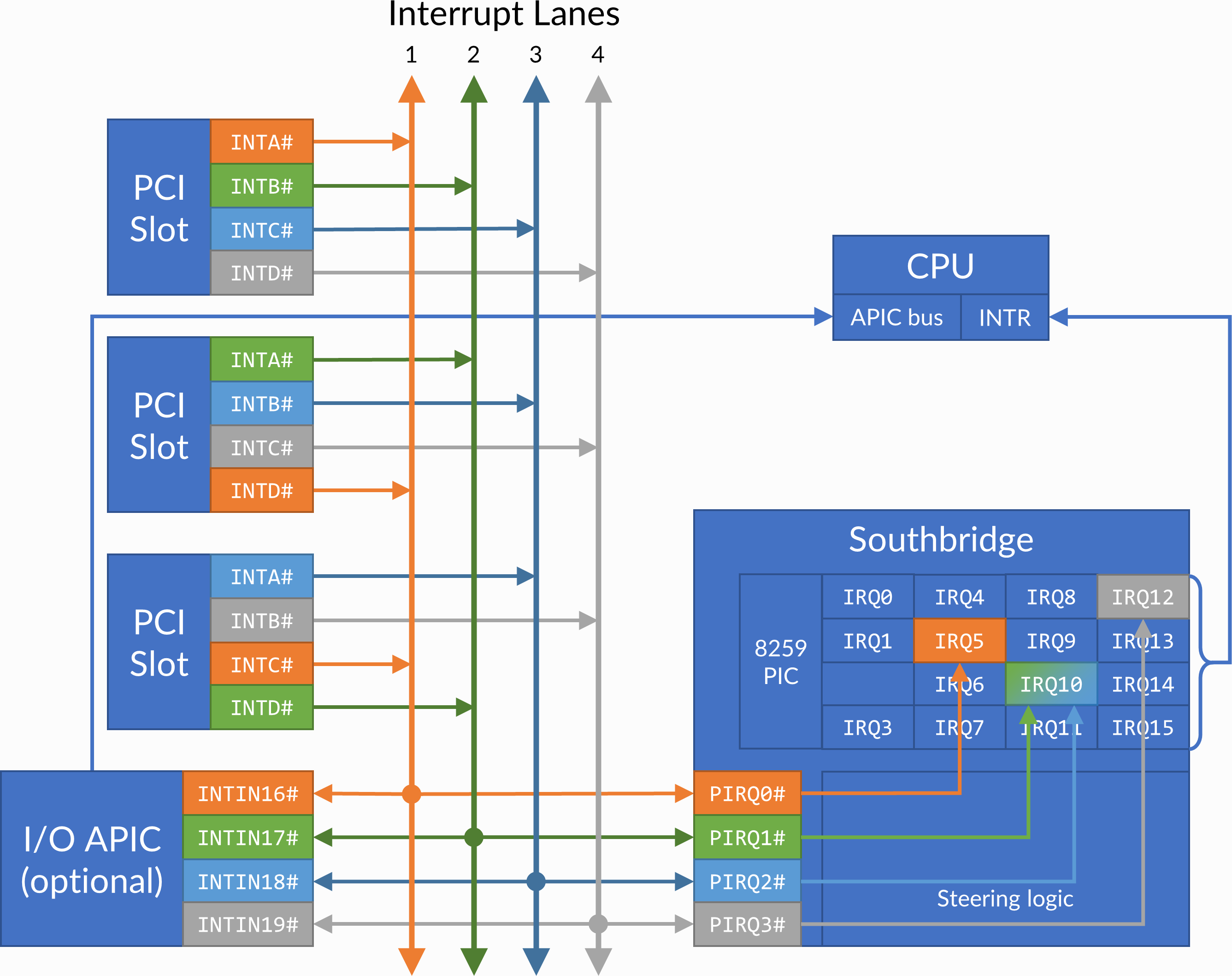
PCI interrupt topology example. IRQ 10 is shared by two interrupt lanes. The machine is free to route any INTx# pin to any lane (sequentially or not), and free to route any lane to any available IRQ.
An emulated PCI device can assert or de-assert an interrupt on any pin with the pci_set_irq and pci_clear_irq functions respectively. The PCI subsystem transparently handles interrupt lane routing (using the per-machine PCI slot table), sharing and steering. Once an interrupt is asserted, a device usually de-asserts it when an interrupt flag is cleared or an interrupt mask flag is set in its configuration, I/O or memory register space.
Code example: PCI interrupts
#include <86box/pci.h>

static void
foo_pci_write(int func, int addr, uint8_t val, void *priv)
{
    /* Get the device state structure. */
    foo_t *dev = (foo_t *) priv;

    /* Ignore unknown functions. */
    if (func > 0)
        return;

    /* The Interrupt Line register must be writable for 86Box to
       know the IRQ to use on machines with non-steering chipsets. */
    if (addr == 0x3c) {
        dev->pci_regs[0x3c] = val;
        return;
    }

    /* Example: PCI configuration register 0x40:
       - Bit 0 (0x01) set: manually assert interrupt;
       - Bit 0 (0x01) clear: de-assert interrupt. */
    if (addr == 0x40) {
        dev->pci_regs[0x40] = val;
        if (val & 0x01)
            pci_set_irq(dev->slot, PCI_INTA);
        else
            pci_clear_irq(dev->slot, PCI_INTA);
    }
}

static void
foo_reset(void *priv)
{
    /* Get the device state structure. */
    foo_t *dev = (foo_t *) dev;

    /* Reset PCI configuration registers. */
    memset(dev->pci_regs, 0, sizeof(dev->pci_regs));

    /* Write default vendor ID, device ID, etc. */

    /* Our device uses the INTA# interrupt line. */
    dev->pci_regs[0x3d] = PCI_INTA;
}

/* Don't forget to add the PCI device on init first, and to save
   the return value of pci_add_card (to dev->slot in this case). */

const device_t foo4321_device = {
    /* ... */
    .reset = foo_reset,
    /* ... */
};
Parameter |
Description |
|---|---|
|
Value representing this PCI device, returned by |
|
Interrupt pin to assert ( |
Motherboard interrupts
Some chipsets may provide steerable motherboard IRQ (MIRQ) lines for on-board devices to use. The amount of available lines depends on the chipset, and the purposes for those lines depend on the machine. 86Box supports up to 8 MIRQ lines, which can be asserted or de-asserted with the pci_set_mirq and pci_clear_mirq functions respectively.
Parameter |
Description |
|---|---|
|
MIRQ line to assert ( |
|
|